Configuration of the Wireless Wire/Cable System
Below are diagrams that show a typical setup for the Wireless Wire system that commucates between valves and the Programmable Logic Controllers (PLCs).
Typical Wireless Cable Network
![Typical Wireless Cable Network - Wireless Wire for Radio Communications Link to Programmable Logic Controllers PLC Typical Wireless Cable Network - Wireless Wire for Radio Communications Link to Programmable Logic Controllers PLC](images/image1.jpg)
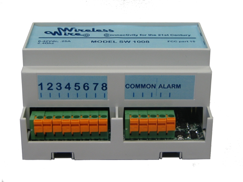
If Contact 1 is closed Valve 1 will be energized.
![If Contact 1 is closed Valve 1 will be energizes - Wireless Wire for Radio Communications Link to Programmable Logic Controllers PLC If Contact 1 is closed Valve 1 will be energizes - Wireless Wire for Radio Communications Link to Programmable Logic Controllers PLC](images/image2.jpg)
If any Contact 2s are closed the PLC is signaled
![If any Contact 2s are closed the PLC is signaled - Wireless Wire for Radio Communications Link to Programmable Logic Controllers PLC If any Contact 2s are closed the PLC is signaled - Wireless Wire for Radio Communications Link to Programmable Logic Controllers PLC](images/image3.jpg)